Chuck Scott – N8DNX
Ham Radio in Northern Michigan
Equipment
Please note that we have replaced the KO8P FM analog repeater with the W8CCE UHF D-Star repeater. We will update this page accordingly soon.
Building
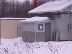
Contained within the unassuming walls of this addition to the main transmitter building are the technical workings of the Stutsmanville Repeater Complex. This addition was built and paid for by local hams and is available for use by compatible non-commercial services.
The building is on a concrete slab and is built to withstand abuse from falling ice. Also notice the metal siding around the lower portion. It seems the porcupines like the wood we used and were eating throug the walls. For some reason, they don’t like the metal quite as much.
Inside
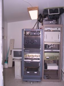 Here’s a peek inside the equipment room. The rack on the right it mostly the 146.680 MHz W8GQN repeater with its duplexer above. At the bottom of that rack is the 443.375 MHz KO8P repeater. The left rack is the controller and the 442.375 MHz N8DNX repeater. The computer to the left of that rack is IRLP node 4450. Needless to say, it’s not quite that simple with remote base equipment and accessories scattered throughout both racks. What you can’t see are the batteries and power backup system behind the racks and the considerable maze of wires, cables, connectors, and other junk in back.
Top of right rack
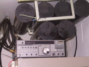 Starting above the top of the rack on the right you’ll see the 146.680 duplexer mounted on the celing. It’s one of a couple custom units we built from several 4 cavity duplexers. They actually provide well more than adequate isolation, but considering that we’re planning on doubling the repeater transmit power soon it may have been a good idea to build them this way.
If you look closely, you’ll see a wire that ends with a piece of copper tubing and some blue heat-shrink tied to the frame of the duplexer. This is a temperature sensor that’s tied to an analog input to the RLC-3 controller and is calibrated in degrees. We can read the room temperature remotely and the controller is set to warn us if the temperature goes too high.
Just below the duplexer is a Yaesu FT-736R that has modules for 50, 144, 220, and 440 MHz installed. This is the VHF/UHF remote base radio. Despite having lost its display and AC supply some time ago, it still functions very well with the remote base system. We can remotely control frequency, mode, offset, and PL as desired. Just below it to the left is an Ethernet switch that’s used to distribute Internet connectivity delivered via a 5.8 GHz wireless link from Petoskey to the IRLP node computer.
W8GQN Transmitter
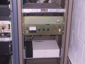
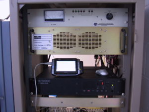 Starting from the top of the right rack you’ll see a power meter panel that’s used to monitor forward and reflected power to/from the W8GQN VHF repeater. It does have threashold monitoring, but we’ve never interconnected that with the contoller. Perhaps someday, if there’s still room for it, we’ll do that.
Just below that is the new TE Systems 170W continuous duty power amplifier. There’s also a circulator that’s now installed (not in the picture) after the amplifier since the amp wasn’t as stable as we needed.
Below the power amplifier is the new TKR-750 repeater the SAARC purchased and installed in July 2006. Sitting on top of the repeater in this picture is my old Vaio UX-280P, which is connected to the serial port of the repeater. (no longer have that computer) Nearly all adjustments and configuration for this repeater are performed using software.
The thin rack below the repeater is a TX/RX band combiner that combines the UHF repeater transmit signals and the VHF repeater transmit and receive signals into a common transmission line to antennas at the 400′ level on the tower. There’s a matching, but weatherproof, unit at the antennas for separating these signals to the VHF and UHF antennas there.
W8GQN Receiver & KO8P Repeater
 This picture shows the rack below the TX/RX combiner. Starting from the top is a Volumax audio compressor. We have two of these, one on the W8GQN repeater receive audio and one on the N8DNX repeater receive audio, to help keep the audio level into the controller for those repeaters relatively constant. This helps bring up the level of our more shy repeater users and keeps the audio alligators at bay. The the one for the UHF repeater can be seen in the rack on the left.
Below the audio compressor is the old GE receiver for the W8GQN VHF repeater and its matching power supply and local speaker. These have since been removed, but I don’t have updated pictures for this part of the rack yet. Yep, lots of open space in this rack now.
At the bottom of the picture is the old KO8P repeater. It was a Vertex VXR-5000 that had performed flawlessly but has now been replaced with an Icom D-STAR repeater (W8CCE-B). The D-STAR repeater runs about 25 Watts, which after all combiner and line losses amounts to only 7.5 Watts at the antenna. Still, it can be heard pretty well from an 8 bay antenna 400′ up the tower and covers nearly 80 miles.
HF Remote Base & WX Receiver
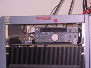 To start with, please ignore that 616… phone number on the label at the top of this rack. It’s been there since I had this rack down-state and I’ve never thought to remove it. I frankly surprised it hasn’t fallen off on its own by now.
Just below that is a Kenwood TS-450S HF transceiver service as the HF radio for the remote base. Like the VHF/UHF remote base radio, users on the remote base system can set frequencies, modes, and even offsets (for 10M FM) as desired. The tape on the controls at the lower right is to keep people (specifically me) from messing with the transmit audio levels.
Just to the left of the HF radio is "Weather Ear" weather radio receiver. It’s programmed to trigger on particular kinds of alert for the counties we cover and is tied to the RLC-3 controller. The controller will bring the alert audio up on the W8GQN and N8DNX repeaters when triggered, record that audio for later replay, and will set an alert tail message on those repeaters. A user over the repeater can also play the current weather transmissions at any time.
N8DNX Repeater Power Amplifier
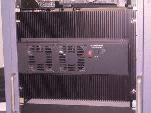
This beefy TPL power amplifier provides punch power for the N8DNX repeater transmitter. This amp is capable of about 250 Watts continuous. I picked it up from the nice people at TPL while at the Dayton Hamvention a few years ago. The story they told me was that this one of a number that were built for a Chineese customer but were never delivered. This amplifier not only has the fans on the front, but also another set of fans to directly cool the amplifier components in the back. It’s currently only producing about 180 Watts due to voltage drop on the DC supply cables that run all the way around to the four deep cycle batteries on the power backup system. We’ll be replacing those cables with something much more robust in the near future. The reason we use the backup batteries to supply this beastie, is that it draws quite a bit of current and the backup system is best setup to handle that.
Controller and More Stuff
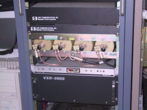
Here’s where it starts to get a bit complicated, so stick with me on this. Located just below the UHF power amplifier is the Link Communications RLC-3 repeater controller. This controller has 8 radio boards and an autopatch. The smaller Link Communications rack just below it is the digital audio recorder used to provide recorded voice messages for the controller. It’s also used to record weather alerts, on-air signal checks, and other such things. This is where all of the on-air help messages are stored for the repeater system.
The duplexer looking thing is a TX/RX UHF duplexer, but we’re not exactly using it for that. Since the N8DNX and KO8P repeaters use separate receive and transmit antennas and transmission lines, they don’t need a duplexer. So, we retuned it and pressed it into service as a transmitter combiner that combines the 25 Watt KO8P transmit signal and the 180 Watt N8DNX transmit signal onto one transmission line (center). That line then feeds the TX/RX combiner in the other rack which in turn sends the transmit signals up the 7/8" hard line shared with the VHF repeater to where it’s again separated and delivered to the UHF transmit antenna at the 400′ level–got it?
For those who need to know, yes, the isolation at 1 MHz (443.375-442.375) is considerably less than at the 5 MHz design separation for this duplexer. Still, it’s more than adequate to separate these two transmitters and provide a clean common signal.
Below the duplexer–errr… ahhhh… combiner–is the Volumax audio compressor for the N8DNX UHF repeater. Just below that is the rack holding the Vertex VXR-5000 used for the N8DNX repeater. That repeater has also provided flawless service over the years and continues for function perfectly. I just can’t say enough good about these Vertex repeaters. As a side point, I also have both of the VXR-5000’s connected to control and analog lines to provide remote control over the "squelch low" line (that essentially make these repeaters more sensitive) and to provide signal level readings back to the controller. Those signal level readings are calibrated to dBm in the controller, which can be read out (both current and peak receive level) by Touch Tone control over the repeaters.
Astron Power Supply
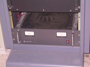 This RM-50M Astron power supply provides regulate 12V power to most of the equipment that needs DC. (You do remember that I said the UHF power amplifier gets power from the backup system though, right?) Behind this elegant panel is an unholy maze of power cables and connectors. The hand print is on the top is likely mine. I guess it’s time for some dusting.
The Inner Workings
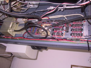 This view of the inner workings of the N8DNX repeater rack looks deceptively organized. I did take considerable care when laying this all out, but things do have a tendancy to slowly grow out of control. In any case, I thought some things here may be interesting.
We’re actually looking at the inside right side of the N8DNX repeater rack with the camera turned sideways. On the right (more toward the top of the rack), you’ll see a panel with rows of terminal strips. These are the analog and digital inputs and outputs to and from the controller all nicely broken out for easy access.
Toward the left of that panel is the UHF receive preamplifier power injector (has the coax connected to it). This injects DC power into the transmission line to power the UHF receive preamp located with the receive antenna at about 470′ up the tower. The circuit board just behind the power injector is a current monitor for the preamp supply. The preamp is an Angle Linear dual redundant high-level unit that’s designed not only to handle very high signal levels, but also to still function even with the failure of one of the two preamps sections. The current monitor is tied to the repeater controller so we can read this out whenever we want. It normally reads about 225 mA, but that can go up a bit when the preamp is seeing strong signals. If a problem occurs in the preamp, the threasholds set in the contoller will detect the abnormal preamp current (high or low) and announce an alert over the air.
Just to the left (below) the preamp injector is some addional DC power distribution and associated fuses. I should really cover those fuses some day. Fortunately the line feeding the fuses is also fused.
To the left (below) of that panel is an old UHF satelite preamp pressed into signal distribution service. It boosts the receive signal from the preamp (that’s lost nearly 15 dB on the way down) to a level where it can be distributed to both UHF repeaters. You can see the signal splitter that feeds these two repeaters connected to the output connector of that amplifer. For extra credit, follow the receive line in from the right (top), through the injector, into the distribution amp, and out through the splitter to the two UHF repeaters.
Power Backup System
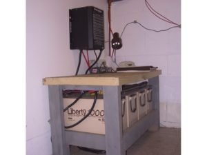
Yes, we have power backup. Should we loose power to the building, which has happened a number of times, this system will keep all our equipment running for a number of hours. Under the bench are four deep cycle AGM batteries for a total of about 400 Amp/Hours capacity. Above the bench on the wall is a "Heart Interface" power inverter and charger. When there’s AC power, the Heart maintains charge on the batteries. When AC power is lost, the Heart will immediately switch in to provide AC power for all of the equipment that’s runing on AC, including the Astron DC supply. Also note that these batteries provide DC power to the UHF power amplifier. The charger in the Heart Interface can deliver more than 100 amps of charge current, so it’s quite capable of keeping up with the load from the power amplifier.
What you don’t see is the little current monitor I built to read out load and charge current. It represents this as a voltage level that’s passed to the controller and calibrated there into amps–although I’ve never been able to get it quite right. The current monitor senses the current across a current shunt at the negative battery terminal. If you look closely, you can just make out the yellow high-current fuse on the possitive terminal of the battery chain. Yes, we do take safety into consideration.
Backup Power on Steroids
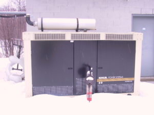 I’m sure most of you with repeater installations have backup power like this at your site–right? This 80 KW Kohler gas generator was installed a couple years ago by the site owner (bless them). Needless to say, the backup system with our repeaters hasn’t had too much of a workout since. It has, however provided power while this thing fires up to bring up AC for the main transmitters in the building behind it. In that building are two FM broadcast transmitters that consume enough power to keep this generator sucking gas when it’s up and running. Fortunately, there’s enough gas on-site to run this thing for about a week. If you’re wondering, the strange looking antenna laying on the ground at the left is an element from a circularly polarized FM broadcast antenna.