Chuck Scott – N8DNX
Ham Radio in Northern Michigan
Ham Radio
My Shack
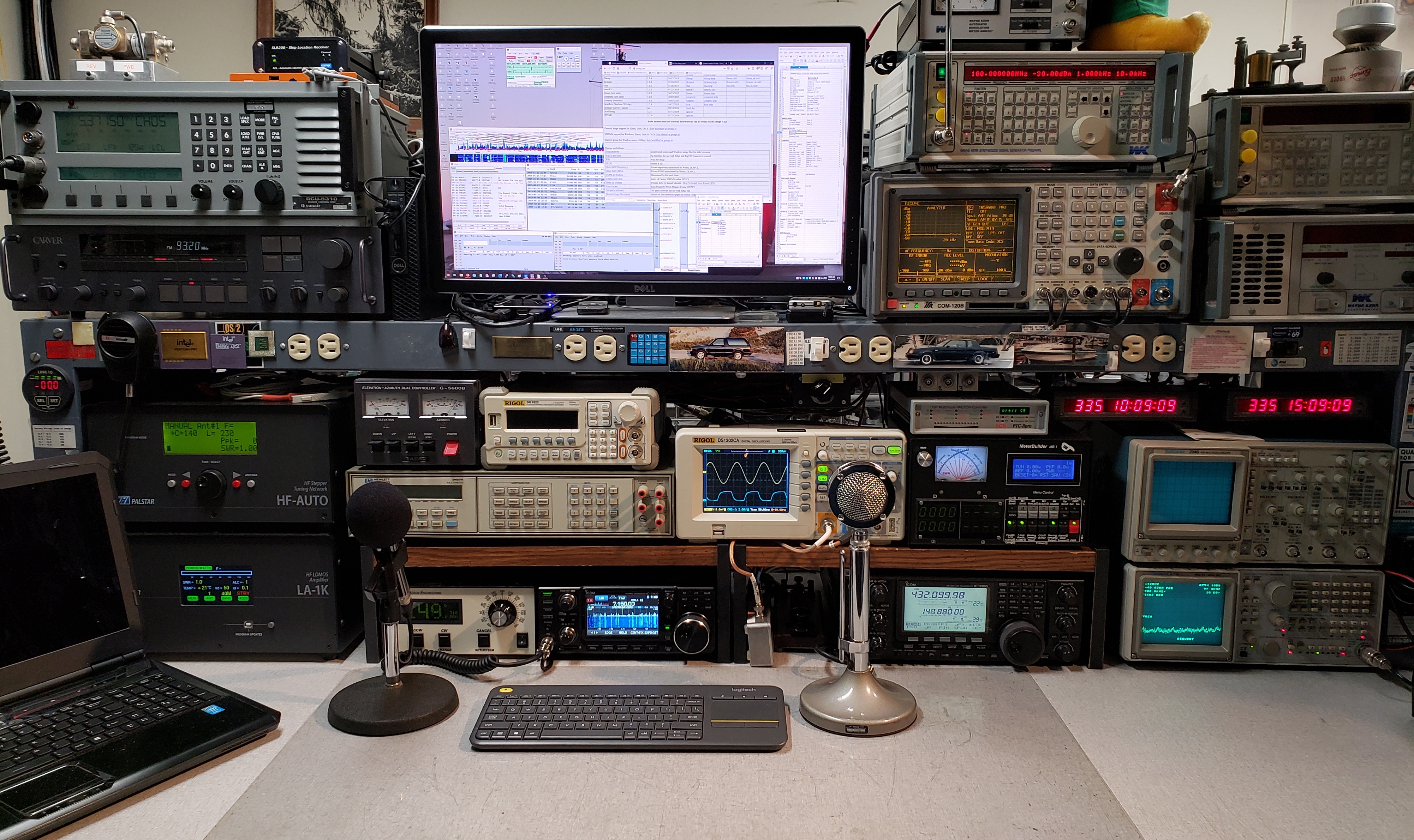
This is part of my “Shack” in the basement and is the bench where most of the fun, and work, take place. There’s also a tool chest to the left that has most of my military radio collection, and to the right it a 19″ wide rack with my DC supplies, Sunair RT-9000 radio and matching 1KW amplifier, a remote controlled receiver, my GPS locked time and frequency reference equipment and at the top the network switch and NTP server. Of course there’s parts bins behind the bench and racks of parts, supplies, test equipment, and other junk in addition to a floor that sometimes is clear enough to walk across.
I recently restructured where all of the equipment is placed on my bench to make it easier to use the things I use most. Normally that would be a difficult task due to having to move everything multiple times to see what fits where. That wasn’t the case though since I’ve been using LibreDraw to plan my bench for some years now.
Basically, I have a drawing that includes rough mock-ups of most of the equipment that I can drag around the drawing. The drawing is to scale in inches and all of the equipment mock-ups are also to scale in inches, including feet and side-handles. This means I can drag things around the drawing and if they fit on the drawing they fit on the bench.
This approach has allowed me to come up with equipment placement that I never would never had tried if I would moving real equipment rather than images on a drawing. This time everything fit where the drawing shows it. I also took the opportunity to completely rewire the back of the bench, which uses Velcro straps to hold most of that. The result of that was a new collection of cables and things that were either not in use or didn’t get re-installed.
Single Point Ground
I recently managed to get in the middle of a discussion on lightning protection in a communications related E-Mail discussion list. I have to say that I was appalled at how much people accept what they’ve been told by others and how little they are willing to re-think things.
While it was a relatively long discussion, the last message I received was the real kicker. It was clear the person had never actually read anything about what a “Single Point Ground” actually is. Reflecting back on other parts of the discussion I realized it might be just that which caused some of the seemingly inconsistent responses I was getting.
So you don’t have to read the whole discussion, here’s my final post. If it doesn’t match what you think a “Single Point Ground” is, then do some research!
Please go read information on “Single Point Ground”!!!
It is NOT some kind of ground for a facility, it is NO part of a lightning or service ground, and radios should NEVER be in the middle of anything!!!
A “Single Point Ground” is a common point through which a group of equipment is exclusively connected. It is a design that simply establishes a common voltage reference point for that equipment and works only if there is no other path for current from that equipment. It only protects that group of equipment and if done correctly will protect that equipment.
Live Long and Prosper — but question everything.
Chuck – N8DNX
Hallicrafters SX-28A
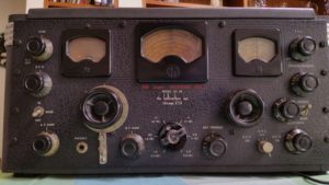 I just acquired a nice Hallicrafters SX-28A. I picked this one up because I had an SX-28 some years ago and it ended up “displaced” when I loaned it to someone who didn’t have the courtesy to hang onto it.
This radio is in pretty good condition but does need some cleaning and minor restoration. I haven’t powered it up yet, but I suspect it will also need some of the capacitors replaced.
One thing I will likely need is a band-switch knob, which is slightly cracked and the sides are angled forward. It also needs a bottom panel to the case that’s missing, but I should be able to fabricate that.
Unfortunately, I don’t have enough time to do a full restoration of this radio, which is really what I’d like. If you know of anyone in the Midwest that does this kind of work and is familiar with the SX-28A, please let me know. Otherwise, I might be inclined to ship it a bit farther if needed.
SEM-52S German Radio
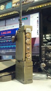 A recent addition to my collection is this German SEM-52S VHF FM radio. It’s a 1980s/1990s synthesized 6 channel squad radio that covers 46 to 58 MHz in 25 KHz steps and produces 1W.
Harder to obtain than it’s SEM-52A predecessor, the improvements the “S” offered were field selectable frequencies for the 6 preset channels using a set of rotary switches just under one of the covers, and the ability to run off of 8 AA batteries.
This one’s in pretty good condition, although the plastic battery case insert that holds the AA batteries did have some damage from leaky batteries that caused most of the metal battery contacts to fall off. No problem, I simply wired in a set of 8 AA rechargeable batteries into the plastic insert and it was off and running.
I have it setup for 51 MHz, which is the common cold-war radio collectors frequency and 52.525 MHz, the standard 6 Meter calling frequency, along with a couple more 6 Meter simpex channels and 2 common military frequencies. The first contact on it with W8NSA about 10 miles away went fine. I did have to adjust the reference frequency trim a bit to get it right on frequency, but nothing else other than the battery pack needed attention.
It appears that I need to loose a few pounds before I can clip the chest strap on the case without cutting off circulation. I believe, however, that I’m really going to like this radio.
I am still looking for any operator or service manuals for this radio in any language — electronic or printed. If you can help, please contact me.
H-250 to SEM-52S
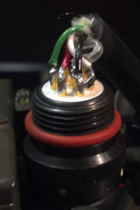 For those interested in the SEM-52S, I just received an NF-7 connector for it and added an H-250 handset to it. It took me a bit to figure out how to connect it up as I found some of the information on-line confusing. So, here’s what I have that works fine.
NF-7  Use       H-250 Color
A     Speaker+  White
  (1K chip resistor between A & B)
B     Speaker-  Black
C     Mic+      Red
D     PTT       Green
E     ?
F     8V
G     Ground    Mic Shield
I believe the colors are pretty standard for the H-250 handsets, but I suggest checking first if you’re going to do this.
Also note the 1K chip resistor I put across A and B on the NF-7 connector for the SEM-52S (right side in picture). This seems to be necessary to get the audio to switch to the headset. Apparently the .9K or so resistance of the handset didn’t do it.
If you have any more information on the handset connector for the SEM-52S and how the various connections really should be used, please pass it on to me by E-Mail (cscott@n8dnx.org) or on the “armyradios” Yahoo Group. If you have an original equipment handset for an SEM-52S for sale (very good condition only), contact me!
D-104 From My Youth
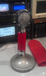 Here’s one of my favorite radio related items. It’s the classic Astatic D-104 microphone I bought when I was a kid. In fact, I remember having my mother drive me to the store to pick this up because I couldn’t drive yet and I was still a month or two away from having my Ham license. That makes this microphone more than 50 years old, which gives you some insight into how old I am.
As you can see in the picture at the top of this page, I’m using it these days. It’s currently connected to my IC-9100 that I use for HF, VHF, and UHF communications of various sorts.
Not only is this microphone still in perfect condition, but the red felt covers are the ones I made for it the very night I bought it. Needless to say, it has special status in my “Shack”.
MEL PRC-2000
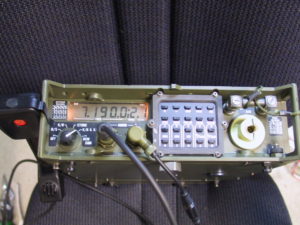
This is a PRC-2000 made by MEL in England that covers 1.6-30 MHz. I love this radio. It’s relatively heavy for a “manpack” unit, but operationally it’s a dream. This radio is what’s called a “TRF” (Tuned Radio Frequency) receiver. That means it has no IF and does no receive mixing. All the receiver stages down to the detector operate at the RX frequency. This makes it a rather unusual design, but seems to give this radio some excellent characteristics.
Not being able to get a remote control handset for this radio, I modified a standard Klansman handset with a 10 position thumb wheel switch for selection of the 10 memories from the handset. A quick project, but a major addition to use of the radio.
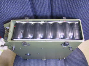
With the 10 AH battery pack I built for this radio, it can run all day and even more if I don’t do much transmitting. This pack is an earlier one I built, but it clearly shows how well a 13 cell pack fits this radio. It’s 13 cells because the radio is nominal 15V and doesn’t like running down below 13V.
No, this radio is not for sale (unless you REALLY, REALLY want it).
Heights Aluminum Tower
 Someone asked me to provide them with old Heights Tower documentation, so I thought I’d post it here.
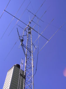
Thought I’d also post a picture of my tower and some of the antennas. It’s not as high as I’d like it to be, but I have lot limitations that keep me from going higher.
This is a Heights aluminum tower with (from the bottom up) a single 6M element, scanner beam and 220 Mhz beam on left side mount with a discone on the top, another discone on the next side-mount, an inverted V (currently a BWD-90), Mosley PRO-67B beam, small UHF beam (barely visible), pair each of 2M and UHF circular polarized beams with elevation rotor, and on the top a Diamond X500 vertical.
It all works pretty well, but I still need a few more antennas. I do usually have an HF vertical at the back of the yard but need to replace the cable going out there that was cut when the sprinkler system was installed. There’s some things that need a bit of minor maintenance now, but since I last put this up (it’s on a motorized hinge base), one tree has grown to the point that I will have to sacrifice the X500 to bring the tower down. Such is life!